History and Future of Nanofibers in Air Filtration
What are Nanofibers?
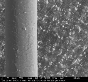
Nanofibers are defined by being a one-dimensional fiber in length. The diameter is so small that the fiber is practically invisible to the flow of the medium being filtered. Different sources cite varying diameters that classifies a nanofiber. Are nanofibers less than 1 micron in diameter? Less than 500 nanometers? Less than 100 nanometers? One practical example I have used to illustrate the scale of a nanofiber is roughly 1000 times smaller than a piece of hair, as seen in Figure 1.
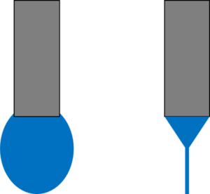
Some physical property advantages that come with having nanoscale fiber diameters include high surface area to volume ratio, high mechanical strength per volume, and the ability to be highly functional. The high surface area to volume ratio allows nanofibers to make a significant impact on the filtration performance with a small amount of material weight added to the filter media. The unique air flow properties come from a phenomenon called “slip flow”, illustrated in Figure 2, that occurs when the surface of the fiber is not large enough to impact the velocity profile through the filter media.

History
The history of what eventually led to the current state of nanofiber production can be traced as far back as the 1600’s. Scientists at that time observed how liquids behaved in an electric field, particularly the fact that the electric field would break the surface tension of the round liquid droplet and form a cone shape. This cone would eventually come to be known as a Taylor cone. In the 1800’s an English physicist named Lord Rayleigh observed liquid droplets ejecting from this Taylor cone. When the liquid is a polymer solution, the polymer chains entangle and link these droplets to form a continuous fiber being ejected from the Taylor cone. The first patent for producing fibers in this way was granted in the early 1900’s. In the 1990’s, the term “electrospinning” was coined and research accelerated, especially by a group at The University of Akron led by Professor Darrell Reneker that was on the forefront of studying the properties of and applications for electrospun nanofibers.
Another example of a nanofibrous media was discovered in 1969 when Bob Gore discovered the properties of stretching (or expanding) polytetrafluoroethylene (PTFE) tape, creating ePTFE. Expanding the tape didn’t immediately cause a break and close observation of the stretched material revealed a network of ultra-fine fibers. This material was initially used in fabrics but applications in filtration started in the 1970’s.
Current State of Nanofibers
One air filtration application that has been successfully using nanofibers is ePTFE media in HEPA and ULPA filters. Slip-flow, enhanced particle capture capabilities, and higher mechanical strength properties have led to the development of HEPA and ULPA filters with lower resistance to air flow at the same filter efficiency class and configuration when compared to conventional microglass HEPA and ULPA filter media.
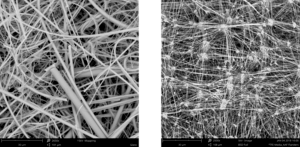
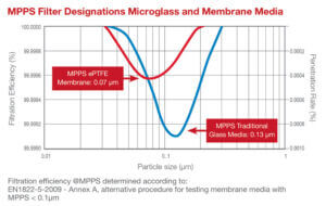
The two SEM micrographs in Figure 4 show that the structure of the ePTFE media consists of smaller fibers and pores, which helps increase the filter efficiency with reduced pressure drop. This combination of properties also leads to the most penetrating particle size (MPPS) of the filter media to be smaller than that of traditional microglass filter media, which will lead to a more efficient filter at most particle sizes, as seen in Figure 5.
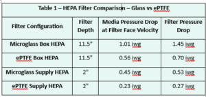
As Table 1 displays, the ePTFE filter media has about half the resistance to air flow as microglass filter media, which leads to the construction of a filter of the same configuration with about half the resistance.
These properties are highly beneficial for filtration applications because end users are always looking for more durable filter media that has a lower pressure drop, however there are some downsides for nanofiber media. One downside is that nanofibers in filtration act as a membrane, or a barrier, so that the particulate being filtered has a very low probability of passing through to the other side. Traditional filter media has depth to it, so particulate has space to accumulate within the filter media. This downside is not of concern for HEPA filtration, where the HEPA filter is a “last line of defense” to ensure a clean space on the downstream side of the filtration system. HEPA filter applications usually have multiple levels of prefiltration upstream to ensure premature loading of the HEPA filter does not occur. However, nanofibers in HVAC filter efficiency levels (MERV rated by the ASHRAE 52.2 test standard) have shown weaknesses when being tested under standard lab test conditions.
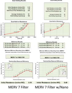
As seen in Figure 6, the addition of nanofibers can boost the efficiency a relatively low efficiency filter media (MERV 7) up to a MERV 11, which has significantly better particle capture properties, particularly with smaller particles that are of higher concern to human health. However, this benefit comes at the expense of higher resistance to air flow (two times increase, from 0.19 iwg to 0.40 iwg) and significantly lower dust holding capacity (more than ten times reduction, from 192 g to 15 g). Part of this is due to the types of dust the filters are challenged with during the lab test and how the filters are tested, there are commercially available nanofiber filters that are able to last long enough in HVAC applications, it is just that the test method isn’t kind to nanofiber filter media so it is difficult to quantify in a lab. There is also an inconsistency that can come from depositing nanofibers on a filter media surface, as seen in Figure 7.
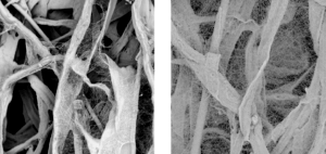
The cause for the variation in nanofiber coating can come from any number of reasons, but there are ways to overcome this by protecting the nanofiber with a support media, or a scrim, that can be used to make a combination filter media. The right combination of filter media technologies can also help solve issues related to pressure drop and dust holding capacity, which leads to where we can go in the future for nanofiber technology.
The Future of Nanofibers
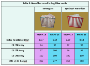
One particulate HVAC filter application that has seen nanofibers used successfully is in bag filters.
In this particular application the filter media manufacturer is able to add three-dimensional surfaces containing nanofibers within a thicker filter media which reduces the pressure drop penalty of using a mechanical nanofiber filter media (the initial resistance is actually less than that of a traditional microglass media bag filter of the same efficiency) and the three-dimensional media also has a high dust holding capacity, equal to or exceeding that of traditional microglass media. Due to the thickness of this type of filter media it is currently limited to bag filter or pad filter media, but these are the types of advancements that can lead to innovation in pleatable nanofiber filter media as well.
Another area that can be improved in the future is how we test filters. As mentioned previously, the current lab tests and especially loading dusts don’t exactly mimic “real-life” conditions the filter will be exposed to in application. Most particles the filters will be seeing under normal atmospheric air conditions are less than 1 micron, but ASHRAE and ISO loading dusts consist mainly of particles larger than 1 micron and even as large as 100 microns. With recent events, such as COVID and wildfires, drawing more attention to air quality, there is a need for innovation in how we test and use air filters. ASHRAE is funding research for investigating a lab filter loading test that better matches atmospheric dust loading conditions, and filter application standards are putting a larger emphasis on using higher efficiency filters. This combination of standards activity and research will drive innovation to develop a better filter that can maintain a high efficiency rating and perform well in HVAC systems.
Author: Jon Rajala, Ph.D., R&D Manager, AAF International
